Ghost,
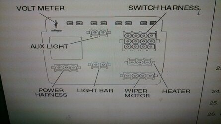
You are correct, but using the sub harness is an easy way to get
switched power out of the factory wiring without have to cut into it.
I am going to use it to activate the isolator for an auxiliary battery.
I grabbed this link to show the harness. Look down in the electrical
accessories.
2016 Honda Pioneer 700-4
John
Maybe I'm not clear on the use of the sub-harness - cause I have no intension to buy the Honda switch plate / harness.
I thought the sub-harness plugs into something else and provides keyed power to the horn and "reverse" power to the backup alarm. I guess I have more homework to do - or just abandon the sub-harness and find what I need somewhere else.
I just wish I had the bloody machine to figure it out
Last edited: