You are using an out of date browser. It may not display this or other websites correctly.
You should upgrade or use an alternative browser.
You should upgrade or use an alternative browser.
P
Tell us more about this gauge install ...........I added a Coolant Temp and Oil Pressure Gauge to the dash.
View attachment 375154 View attachment 375155
I'm Working on it. I'll write it up when I get it all done and bugs worked out.Tell us more about this gauge install ...........
Dirtstiffs-1000
Well-Known Member
Lifetime Member
Supporting Member
- Nov 3, 2018
- 1,729
- 6,241
- 113
- Ownership
-
1000-5
M
Installed SATV’s frame stiffener today and took the opportunity to install rivnuts for my skid plate while it was off.

Christmas finally came! Gotta love “2 day free shipping”  the $100 Chinazon soft top for this summer!
forgot to mention, that was ordered in October. Lol

forgot to mention, that was ordered in October. Lol
Last edited:
Dirtstiffs-1000
Well-Known Member
Lifetime Member
Supporting Member
- Nov 3, 2018
- 1,729
- 6,241
- 113
- Ownership
-
1000-5
@Moxdmguy I am getting ready to do this myself. What size rivnuts and length of bolts did you use?Installed SATV’s frame stiffener today and took the opportunity to install rivnuts for my skid plate while it was off.View attachment 379471
M
I went with M6 rivnuts and 1 inch flange bolts. Used 1-1/2 inch bolts where the two spacers are required for the SATV full skid plate.@Moxdmguy I am getting ready to do this myself. What size rivnuts and length of bolts did you use?
advertisement
I started a project some time ago to add and engine oil pressure gauge and coolant temperature gauge to my 2016 P1000-5D. I had to break this into TWO parts, because, according to the site it was "too long to post" This is part 1 with part 2 to follow.Tell us more about this gauge install ...........
The lack of an actual engine oil pressure gauge was troubling. The Oil pressure light on the dash is actually controlled from the Main trans pressure sensor or the "Clutch Line EOP Sensor". This sensor does not actually read the ENGINE main gallery oil pressure as the trans clutch pressure circuits are almost completely separate. The HONDA system works on the ASSUMPTION that if you have trans clutch pressure, you must have engine main gallery oil pressure. This can be a bad assumption in some cases. For instance, you might have a serious failure of some part that is exclusive to the Engine oil pressure circuit, like a stuck pressure relief valve, damaged engine oil pump, bearing failure, etc. You CAN have Good clutch pressure and still have low engine main gallery oil pressure (ask me how I know this to be true).
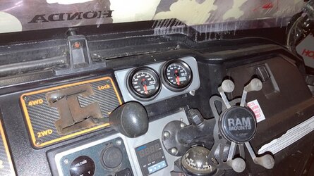
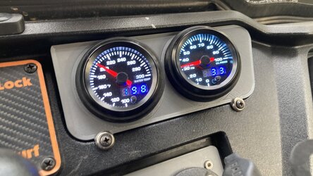
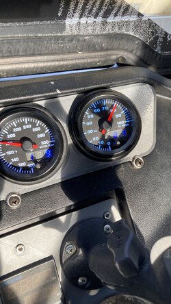
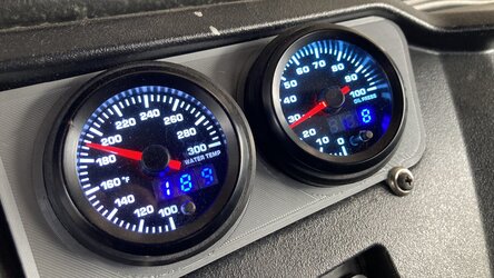
I Bought some suitable gauges from Amazon. I went with electric gauges on this install. I did test with a mechanical gauge but found that getting the oil pressure line run to the dash was going to be a pain. It was just much easier to run the sensor wires. The gauges I got were not the cheapest, but they also were not top of the line. These gauges have the ability to indicate with both a dial and an LED digital display. Illumination color of the dial faces is controlled by a push button on the front of the gauge. You can select from many colors. The picture above shows the "white" gauge color. These gauges are actually stepper motor driven gauges, so should be more vibration resistant. Spend as much as you like on gauges.
After getting the gauges, I designed and 3D Printed a mount that fit into the upper cubbyhole on the dash.
The panel is secured to the dash with two screws and is easily removable for service or replacement of gauges.
I fabricated an adapter to go from 8mm thread on the main oil gallery plug to 1/8 NPT to allow the pressure sensor line to mate to the oil gallery. I used the rearmost plug as it could be easier to access without removing a lot of parts. Still not a perfect solution as it does get in the way of the dipstick. This may bother some people, however, I find the dipstick pretty much a joke, and the engine does not use or leak oil. I just change oil regularly, add the correct amount of oil to the oil tank and send it, never had an issue. I can disconnect the oil pressure sensor line if I want to use the dipstick. No big deal either way. I used to oil pressure test point in the red square. You could access the one below the starter, but this requires more time and makes changes difficult if something goes wrong. This is still a test, after all.
see part #2
Last edited:
Part #2 of my Gauge install P1000-5D 2016:
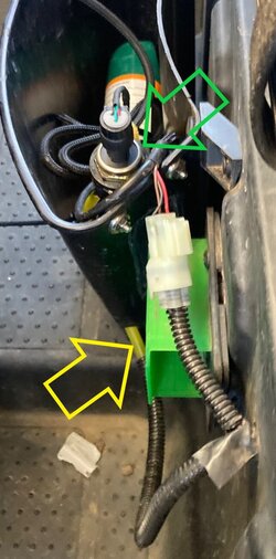
The oil sensor transducer mounts in a more convenient location (for the moment) up front to easily attach the 12V supply, Ground and Output to Gauge wiring harness (transducer is indicated by green arrow below). The sensor is connected to the Engine by a short run of 1/8" tube instead of being crammed in directly above the dipstick (tube runs inside the sheath indicated by the yellow arrow below). I do not believe it would have been possible to install the access cover with the transducer in that location. This 1/8" line was a shortened portion of my original (temporary) mechanical gauge test installation. This may be changed in the future if problems arise.
All of these gauges are powered from my accessory fuse panel, key on, gauges are on. All sensors and gauges use a common ground at the fuse panel. All wiring is High temperature automotive grade stranded copper; properly terminated and insulated, no "scotch locks" or "wire nuts". Wiring is covered in split loom or other suitable protection as well as being secured to existing harness as needed. This prevents chafing and other damage to the harness and tubing.
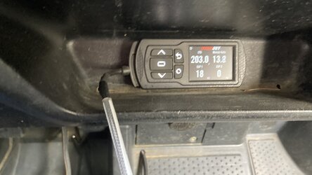
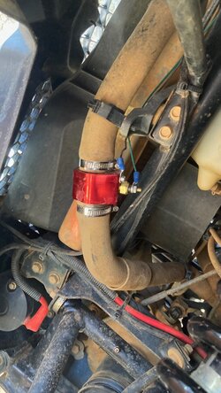
The coolant temp sensor was easier to mount. I used a 26mm inline hose connector with a 1/8FPT opening for the sender. Mounted this in the upper Coolant hose from the engine thermostat after cutting out a section of the hose equal to the length of the connector. This should be the hottest part of the cooling system outside of the location of the engine temp sensor. This adapter is also grounded to the same buss bar as the other grounds of the system. Since I have a PV3, I can compare the readings from the original HONDA sensor. Once warmed up, the sensors normally read within 2 or 3 degrees of one another. In the event of "low" coolant, the temp gauges will show considerably different temps, depending on which sensor is not being exposed to liquid coolant. An air bubble at the engine sensor or the thermostat will cause that reading to be lower than normal.
Feel free to ask questions.


Last edited:
P
Nice write up, thanks a bunch for taking the time .....
G
Nice upgrade.
Could you please list what items you purchased - gauges and sensors.
If I understand correctly, oil is under pressure on either one of the bolts you show on the engine and could be used to connect the oil pressure sensor? These two bolts are only plugs?
Could you please list what items you purchased - gauges and sensors.
If I understand correctly, oil is under pressure on either one of the bolts you show on the engine and could be used to connect the oil pressure sensor? These two bolts are only plugs?
These are the gauges. They are NOT top of the line, but should be good enough for this test. I did have one DOA gauge, but they replaced it at NC. If they give any more trouble, then I can upgrade later on.Nice upgrade.
Could you please list what items you purchased - gauges and sensors.
If I understand correctly, oil is under pressure on either one of the bolts you show on the engine and could be used to connect the oil pressure sensor? These two bolts are only plugs?
The two plugs on the left side of the engine are test ports for the oil pressure. Both are direct paths to the main engine crankshaft oil gallery. This is where you will find the actual engine oil pressure.
G
Thanks for the info. Could I bother you one more time for info on the temp & oil sensors?These are the gauges. They are NOT top of the line, but should be good enough for this test. I did have one DOA gauge, but they replaced it at NC. If they give any more trouble, then I can upgrade later on.
View attachment 379709
View attachment 379708
The two plugs on the left side of the engine are test ports for the oil pressure. Both are direct paths to the main engine crankshaft oil gallery. This is where you will find the actual engine oil pressure.
Scoop
Well-Known Member
Lifetime Member
Supporting Member
Thanks for the info. Could I bother you one more time for info on the temp & oil sensors?
The gauges come with the sensors. All in one box!Thanks for the info. Could I bother you one more time for info on the temp & oil sensors?
W
What did I do with my pioneer today? Well for starters I spent about 3 hours trying to get the rear diff lock adjusted so that turf mode would work. They changed the diff control for 2022 and I have to say the new one is easier to access but needs to be a lot more finely dialed in to get it to act right. We’re talking about 0.25 millimeters of difference (in the gap between the two pieces in the adjustment apparatus) between it functioning perfectly and it either staying locked all the time or unlocked all the time regardless of 2wd/turf mode lever or gear lever position. I’ll save everyone some time. It’s easier to get right if you put it in 2wd (locked) and make sure it’s locked BEFORE you put it in park/turf mode to adjust per the manual. I had it up and down on jack stands for the first 2 hours before I realized it was not actually engaging the diff lock in park so I wasn’t getting a proper reference point on where to start making adjustments. This by the way is on a machine with 10 hours on it. I’ve never seen one this far out of adjustment from the factory… it was at least 3 full turns too loose at first so would not unlock even though the dash was showing it as unlocked. So just FYI for anyone who upgrades from a pre-22 to a 22+ model.
After that I spent about 30 minutes installing RB3 door bushings on all 4 doors and adjusting the bed latch (also slightly different for 22+) and now it’s squeak free. So at least one part of the “fun” afternoon I had planned went well lol.
After that I spent about 30 minutes installing RB3 door bushings on all 4 doors and adjusting the bed latch (also slightly different for 22+) and now it’s squeak free. So at least one part of the “fun” afternoon I had planned went well lol.
advertisement
Similar threads
- Replies
- 34
- Views
- 2K
S
- Replies
- 5
- Views
- 683


