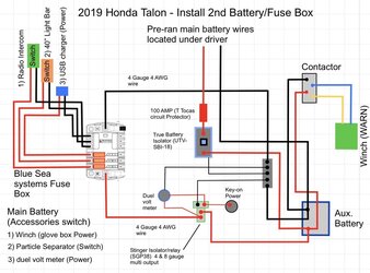
The winch fwd/rev direction switch wiring instructions should show its +12v wire connected to a key-on voltage source, the Honda accessory harness.
I am considering this same circuit. When the engine is running and alternator voltage above 12v, the True isolator is a relay that picks up and connects both batteries together in parallel. Both batteries are charging at the same time. If the draw on current, the total electrical load (winch and anything turned on at any moment) exceeds what the engine/alternator can provide, the electrical system dc volts will pull down to or below the battery volts (12v plus) at which time the two batteries and alternator are working together to provide the demanded current in amps. If the load and current draw is so much that the electrical system volts drops below the True isolator trip point, that relay will open and separate the two batteries.
Anything wired to the aux battery will only get power from the aux battery and risk running it out of charge. The aux battery voltmeter would now be much lower than the primary battery voltmeter.
When the load (winch) is shut off, the electrical system will jump back up to above 12v to the alternator voltage, True isolator relay will energize and connect the batteries in parallel again and both batteries will resume charging.
Also if the engine is switched off, the True isolator opens the relay and the aux battery is disconnected (the 12v “hot” positive terminal) from the main battery. So, whatever equipment connected to the aux battery cannot draw power from the main battery.
This is where the Stinger relay does it’s job. If the ignition key 12v is off, the stinger relay cuts power to the Blue Sea or whatever brand fuse box is there. In this example diagram, nothing can get power if the key is off. If there is something like an audio system or lights you want to be able run with the key off, it would need to be wired on the “hot“ side of the stinger relay, which is directly to the aux battery positive terminal. Even if the aux battery is drained down, it cannot take power from the main battery, which keeps the main battery ready to start the engine.
This is my reading of the electrical diagram. Like to hear if somebody has tested a circuit like this to see it working. I think it’s very important to have the two voltmeters and be able to see the True isolator indicator light. It would be easy to wire this a little wrong and not get the full benefit of the protection. Sorry for writing this book in my forum post!


